Physics
Chapter 21: 6-15

Web Lecture
Transforms and Inductance
Introduction
I am busy just now on Electro-Magnetism and think I have got hold of a good thing but can't say: it may be a weed instead of a fish that after all my labour I may at last pull up.
Michael Faraday, Letter to R. Phillips on 23 Sept 1831 after observing the first evidence electric current in one wire could induce current in a second, unconnected wire.
Outline
Generators and Transformers
Spinning a magnet creates a constantly changing magnetic field, and an continuous emf. The resulting current, however, is changing direction and magnitude with the direction of the magnetic field, resulting in alternating current. This current can be used to power electric devices, however, so magnetic induction of alternating current is the primary source of electrical power in the Western world.
Generators
From our previous discussions, it should be obvious now that if we need a magnetic field, we run current through a wire, and if we need electricity, we wave a magnet around near a wire, or wave a loop of wire around near a magnet. Of course, getting reliable current of a particular magnitude and direction would be most practical, so we need a mechanism that will allow us to
- minimize the weight of whatever moves to reduce the energy required for movement
- maximize the rate of change of the flux
- control the direction of the generated current
In practice, then, we often find the electrical generator uses a pair of very large magnets to create a magnetic field. Within the space between the north head of one magnet and the south head of the other, we place a single wire with as many loops as we can pack. We use some kind of mechanical power to turn the loop (like water falling on paddles), and we have the wire leads attached to some conducting mechanism:
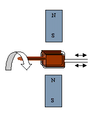
The wire coils wrapped around the block turn when the block is turned, creating a magnetic flux situation, because the surface area they present to the field is constantly changing. The amount of current changes as well, since at any instant it is a function of the total area. Moreover, the direction of the current changes, since as the loop rotates, it changes orientation with respect to the constant field. This design produces an alternating current, where the energy generated from the flux is
The length of the loop across the field is not changing, but the height of the loop's face in the field is changing as the angle between the surface and the direction of the B field between S and N changes: h = v sin θ, The force of the magnetic field thus compels charge along the lengths l at the top and bottom of the wire, but (because of the direction of motion of the loop), the force along the sides of the loop is toward the side of the wire, not along its length. So we consider the 2 l segments and the changing v sin θ. If we consider θ as a function of time, we have θ= ωt. Our equation becomes
Now v itself can be expressed as a function of w: v = w(h/2), so we now have
If we increase the number of coils N, the size of the mag field B, the area of the loop A, or the rate of rotation w, we can increase the amount of emf generated in a time t. Engineering a good generator consists of maximizing these factors within the limitations of resources and safety.
Transformers
The emf produced by a generator may not supply the appropriate current for a given electrical device. In this case, a transformer is used which changes the amount of current supplied into some other amount. We recall that the emf induced in a wire depends on the number of coils. Suppose that we have wire A, conducting current from some supply, and we loop it around a magnetically susceptible material, such as a soft iron core ring. The input current in the wire will cause a magnetic flux through the core, and the flux will be proportional to the number of loops of wire A around the core.
Now we simply loop a "pickup" wire B around the opposite side of the core ring. The magnetic flux in the core induces current in wire B that is proportional to the number of loops of wire B around the core.
This is what the little black box between the house outlet and your Sony Discman or computer is doing: turning 120V household current into 9V current that won't burn out your delicate electronics. We can determine the number of coils needed by looking at the input device's current and coils, and the desired output current.
Ioutput/ Iinput = Number of coils of input wire / Number of coils of output wire
Practice with the Concepts
Discussion Points
© 2005 - 2026 This course is offered through Scholars Online, a non-profit organization supporting classical Christian education through online courses. Permission to copy course content (lessons and labs) for personal study is granted to students currently or formerly enrolled in the course through Scholars Online. Reproduction for any other purpose, without the express written consent of the author, is prohibited.